Centerless Grinding
Centerless grinding is often viewed as overly complex, but a look at the process’ fundamentals reveals otherwise
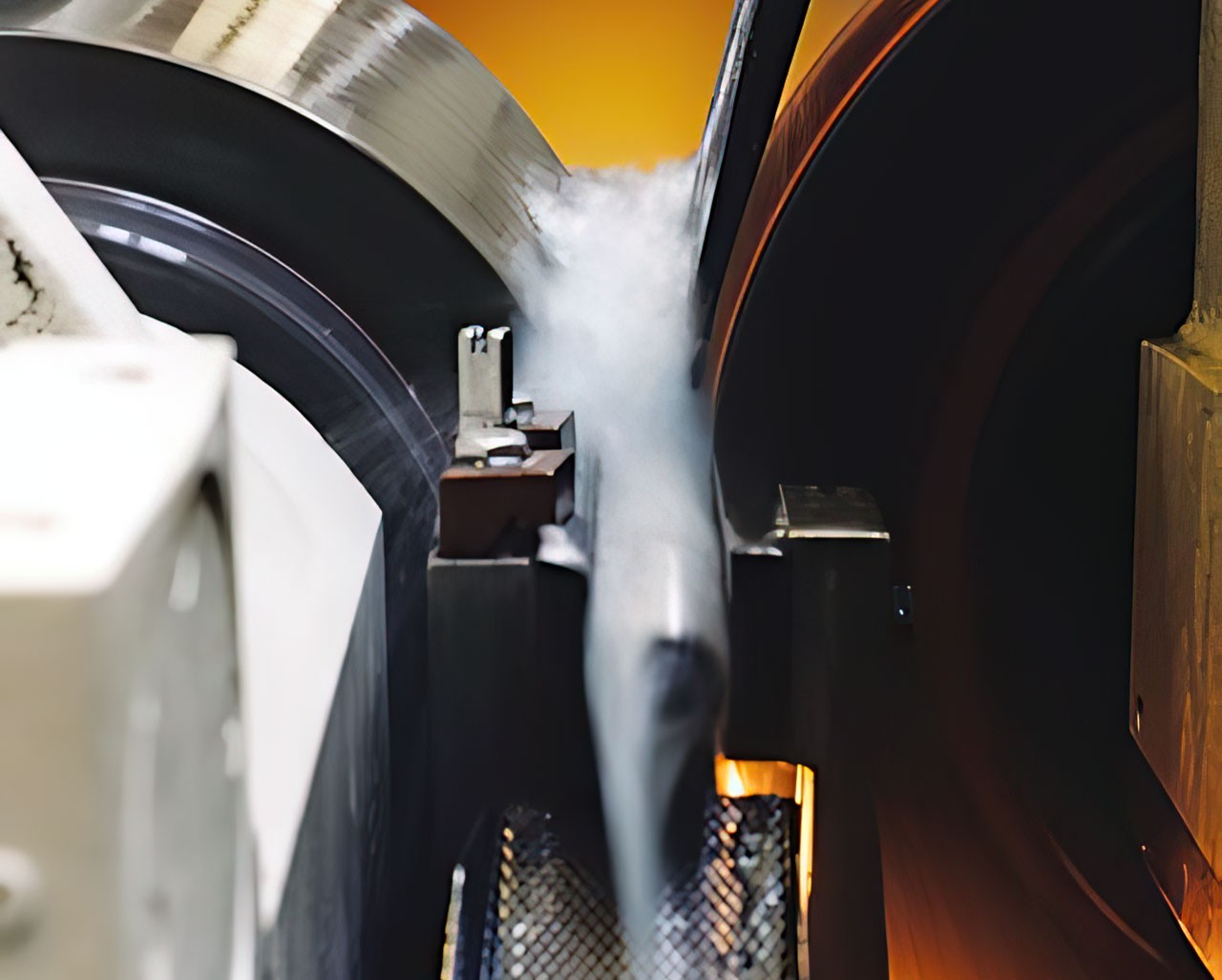
Shaping materials by grinding them with hard, abrasive particles is arguably the oldest manufacturing process. Despite its long history, grinding is often seen as shrouded in mystery because of the numerous cutting points and their irregular geometry, the small DOCs that vary from grain to grain and the sorcerous sparks shooting off the wheel. Grinding a workpiece that’s not supported between centers by a headstock and tailstock only adds to the darkness. “Centerless is considered the black magic of grinding because it’s not as straightforward as putting a part on a fixture and then just moving a wheel,” said Mark Bannayan, marketing manager for centerless grinder builder Glebar Co. Inc., Franklin Lakes, N.J. But centerless grinding doesn’t have to be misunderstood. “You have to develop the skill level for centerless and then it becomes a day in, day out operation,” said Mark Schram, president of Ace Grinding, Melrose Park, Ill., a custom centerless grinding shop. “It’s not really a difficult thing to do.”
Centerless Basics
A centerless grinder has three main components: a grinding wheel, a regulating wheel and a work support blade. Because the entire workpiece is supported by the regulating wheel and the blade, centerless grinding provides a more rigid system, enabling more efficient and accurate grinding compared to grinding between centers. “If you’re trying to grind a ¼”-dia. bar between centers, it’s very difficult because the bar wants to move and flex,” Schram said. “In centerless grinding, there’s no flexing because the workpiece is supported on three points. The workpiece is rotating but not moving its position.”
Ace is the Place for Custom Centerless
Established in the early 1950s and owned by the Schram family since the late ’70s, Ace Grinding provides custom centerless grinding, specializing in machining titanium, and straightening of bar stock. “About 80 percent of what comes from the mills we have to straighten,” said Mark Schram, the president of the Melrose Park, Ill., company, which also operates a smaller facility in Franklin Park, Ill., to handle Ace’s infeed centerless jobs.
The bar stock Ace grinds is from 0.030″ to 6″ in diameter and up to 24′ in length, but it limits bar lengths to 6′ or less when grinding the smallest diameters. The titanium bar stock is generally smaller rounds, requiring a tolerance of ±0.0005″ and a surface finish of 16 or 32 rms. When processing titanium, multiple passes are almost always required and it runs at a slower speed than other materials, such as 12L14 steel. “Everything is different,” Schram said about grinding titanium.
Some of Ace’s work for the medical industry requires bars to be heat treated before restraightening and regrinding, and the shop sends those out of state to a heat-treat facility that can handle up to 12′ lengths. Ace buys remanufactured Cincinnati centerless grinders when its needs a “new” machine. The shop’s latest acquisition was remanufactured by Always Precision Inc., Plainfield, Ill., and came equipped with a laser gage that measures a ground bar and adjusts the grinding and regulating wheels via a CNC-actuated servodrive. “That machine was probably originally made 25 years ago,” Schram said. When Ace purchases a remanufactured grinder, the shop trades a machine in. “I could end up buying my same machine back 10 years from now,” Schram said.
He noted that Ace has about 20 machines and runs two shifts, operating up to 20 hours a day plus Saturdays when busy, but not all the machines run at night. The company employs nearly 20 workers. “We’ve got a really stable workforce,” Schram said. “We’ve replaced one person in the last 6 months.” Retaining workers is important as finding qualified help is difficult for manufacturers in general and centerless grinding shops in particular. Schram said: “In centerless grinding, your hands get dirty. A lot of people don’t like doing that anymore. And it takes a long time to be a top setup man in centerless grinding.”
To enhance productivity without adding staff, Ace is automating more processes so one person can operate multiple machines. That includes automating bar load and feed operations, which Ace designs and builds the equipment for in house, as well as newer technologies. “That’s where the laser gauging comes in and makes it a lot easier for the guys,” Schram said. “They can look across the room and see if the machine is running correctly.”
The grinding wheel can contain conventional abrasives or superabrasives and has a larger diameter than the regulating wheel. Also known as a drive or feed wheel, the regulating wheel controls the workpiece’s speed, preventing the workpiece from speeding up and rotating at the same speed as the grinding wheel. That enables the grinding wheel to remove material from the workpiece. Although a regulating wheel might have some abrasive grains in it, it is typically comprised primarily of a rubber-type bond material and doesn’t perform grinding. Other regulating wheel materials include stone and knurled steel.
The regulating wheel rotates clockwise in the same direction as the grinding wheel, but at a much slower speed. For example, a regulating wheel’s speed might be 30 rpm while the grinding wheel is rotating at 1,300 rpm. “If the regulating wheel fails to do its job, you lose frictional drive from the regulating wheel, the grinding wheel takes over and the part speed will be controlled by the grinding wheel speed,” said Greg Payne, centerless product manager for Cinetic Landis Corp., Milford, Ohio. While 85 to 90 percent of workrest blades are carbide-tipped materials, other materials, such as ceramic and bronze, are sometimes used, according to Payne. The blade angle varies by application—going from a flat blade for some bar grinding operations to as high as 45° for some small, intricate finishing work—but the most common angle is 30°.
“The function of that blade angle is to promote roundness generation,” Payne said. “The angle helps to not let the part drop an amount that’s equal to how much you removed from the high spots. It kind of cancels that out. The higher the angle, the faster it helps to provide roundness correction, but there are limitations.” As a blade wears, a groove forms, which can cause profile problems. To prevent that, the blade is reground to the desired angle and flatness. Shims can be used to adjust blade height, but other methods are available. For example, Bannayan noted that Glebar offers a ramp mechanism on its machines where an operator turns a setscrew to raise or lower blade height.
Centered Grinding on a Centerless
Some grinding professionals consider performing center-type grinding and centerless grinding in the same machine suitable for only very special applications, but it’s frequently done according to Frank Warthun, senior product manager for United Grinding, Miamisburg, Ohio. The machine tool builder offers the 6-axis Kronos L dual from Studer Mikrosa GmbH for these applications. With the Kronos L dual, the workpiece center remains intact because of the combination of two grinding methods, according to the company. In addition, the workpiece is fully supported and therefore cannot bend.
Warthun noted that grinding between centers is appropriate for parts that require a high level of roundness accuracy on the diameter related to the centerline, such as for bearings and transmission shafts. Centerless grinding is suitable for parts with a roundness requirement less than 1μm and when part quantity is suitable. “You can’t just do a couple hundred; you need a couple thousand,” Warthun said.
“I normally explain to customers that we are going to split a micron by a third,” Warthun added. “You just come in with the grinding wheel and grind these parts related to the centerline on the diameter, retract the tailstock and the part will fall down to the workrest plate and then you centerless grind it.” Standard live or dead workhead and tailstock centers are used, and the workhead does not necessarily need a driver and programmable rotational speed. “Clamping between centers provides enough pressure on the part that the part will be broken down in relation to the OD grinding wheel,” Warthun said.
The Kronos S centerless grinder is another centerless grinder from United Grinding, which provides economical processing of small parts, according to the company. An end user can convert the machine from any setup into a 15° inclined plunging machine within 2 hours, including dressing. This enables applications that were only possible between centers to be ground centerlessly, such as for diesel injection needles and bearing housings. In this way, the Kronos S is “two machines in one,” stated United Grinding.
Another alternative is available from Micron USA Inc., Kentwood, Mich., which offers a flexible slant-bed machine for quick changeover on throughfeed applications, according to Brad Darr, manager of North American sales and marketing for the grinding machine builder. The regulating wheel’s lower slide is set at 15°, and the upper slide is parallel to the ground. By manipulating the two slides simultaneously, the end user is able to raise or lower the regulating wheel centerline, maintaining the workpiece contact point with the regulating wheel. “For example, when going from a 40mm-dia. part to a 65mm-dia. part, we have the capability of changing the regulating wheel center height through the CNC rather than manually changing the rest blade height, greatly reducing one’s changeover time,” he said.
Types of Centerless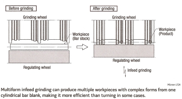
Two basic types of centerless grinding exist: through-feed and infeed. According to Payne, through-feed centerless grinding is the most common. As an example, it is often performed to prepare bar stock for Swiss-type machines. In through-feed grinding, a workpiece is inserted between the regulating and grinding wheels, causing the workpiece to rotate and move forward. To provide the workpiece with suitable rotation and feed, the regulating wheel is tilted from the horizontal plane, with the end of the wheel where the workpiece enters being higher. The larger the feed angle, the faster the workpiece travels between the wheels. Because the regulating wheel is tilted, it has to have a hyperbolic shape—a slightly hollowed center—so the workpiece contacts a straight line across the regulating wheel’s face. “If the regulating wheel was a constant, true cylinder, the workpiece would only hit the center,” Payne said.
The second type of centerless grinding is infeed grinding, which is sometimes referred to as plunge, profile or end-feed centerless grinding. The infeed method is for workpieces that require multiple diameters or steps. Here, the grinding and regulating wheels are dressed to match the finished part’s dimensions. In addition, infeed grinding is for workpieces that have a projection that prevents through-feed grinding. When infeed grinding, a workpiece is placed on the rest blade between the two wheels, a work locator, or “end stop,” blocks the workpiece from traveling axially during the grinding cycle. Like through-feed grinding, infeed grinding is geared towards high-volume production, but the through-feed method generally grinds parts quicker. “The only parts you grind infeed are the parts you have to,” Payne said.
Valve spools, pump shafts and engine valves are examples of parts that are suitable for infeed grinding. Schram described one Ace Grinding job producing a bone screw drill bit for the orthopedics industry that requires the part’s three diameters to be ground simultaneously. “It’s turning into a really nice but difficult job,” he said. “When surgeons are turning that drill bit, it can’t wobble. The TIR on the part has to be very uniform.”
Other Applications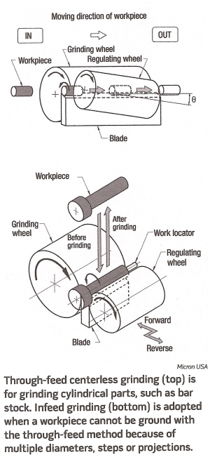
Infeed centerless grinding can also produce the carbide and steel blanks for making industrial cutting tools and punches and core pins for the moldmaking industry. That’s the primary application for the centerless grinders from Tru Tech Systems Inc., Mt. Clemens, Mich., according to Ryan Michels, sales manager. Compared to a larger, conventional centerless grinder, he said setup is quicker and easier on Tru Tech grinders. “You can get a pretty good setup in 5 to 10 minutes,” Michels said.
He noted that software simplifies the process. “It talks to you and walks you through the setup process,” Michels said. “It tells you what to do and when to do it.” The software also incorporates a library of help videos to explain how to fix specific problems, such as correcting wheel runout and wear. Modules are available for making trigonometry and radius calculations, and a database of speeds and feeds is available to help impart optimal surface finishes. Setup on Tru Tech machines is also fairly quick, according to Michels, because they can use 1A1 grinding wheels, which are flat and usually measure ½”×7″—smaller than most centerless grinding wheels. The flat wheel, for example, can plunge a workpiece to produce a part’s rough form and then profile it with angles, radii, back taper and a drill point in one setup. Unlike a typical centerless grinder, Tru Tech’s grinders use a bearing arm with a roller bearing on the end of it to hold the workpiece similar to a V clamp. A motor turns the roller, which in turn spins the part.
In addition to being able to quickly set up different infeed grinding jobs, Michels said switching from infeed to through-feed on the machines takes about 10 to 15 minutes. Centerless grinding has also been used to produce parts previously thought of as only suitable for other manufacturing methods. Glebar’s Bannayan noted the example of centerless grinding three different tapers down to 0.002″ in a 0.012″- dia. guide wire that carries a stent to a blocked artery. Previously, the wires were produced with chemical etching, removing the wire from the chemical at specific time intervals to create the tapers.
“We were able to introduce the centerless grinding process to it and do it a hundred times quicker with much more flexibility as far as the shapes of the wire,” said Bannayan. He added that centerless grinding is also suitable for some small-diameter parts typically produced on Swiss-style turning centers.
Centerline Matters
Whether through-feed or infeed centerless grinding, the centerlines of the regulating and grinding wheels are at approximately the same height, with the grinding wheel slightly higher for some applications. However, the workpiece centerline must be higher than the other two to avoid producing tri-lobed diameters. “The most dangerous point in centerless grinding is when the workpiece centerline is exactly in line with the centerline of the grinding wheel and feed wheel,” said Schram. That’s when centerless grinding generates high points on a workpiece diameter, and those high points start magnifying as the part rotates, generating progressively smaller low points on the opposite side as a high point hits the feed wheel and pushes the workpiece into the grinding wheel, he explained. If the setup is incorrect, “centerless grinding is notorious for threepoint out-of-round with a bad setup,” Schram said. “It’s also very good at fixing three-point out-of-round as long as the setup is correct.”
With knowledgeable centerless setup personnel in short supply, software can sometimes help. “It’s not real critical as far as centerlines go because with our software we usually can compensate for any human error in the setup,” said Tru Tech’s Michels. “It’s quite forgiving.” As a builder of new centerless grinders, Payne said Cinetic Landis designs and manufactures its machines with the spindles’ centerline heights to be precisely in line with one another, which becomes more critical as part diameter decreases, but rebuilders frequently overlook that during the rebuilding process.
Payne added that a remanufactured centerless grinder has the same static stiffness as when it was originally built, but a new machine usually has significantly higher static stiffness because of its advanced design, which is beneficial when processing hardened metals and achieving tight tolerances and high throughput. For example, he said an old Cincinnati centerless grinder has a static stiffness from about 300,000 to 800,000 lbs. per inch, depending on the model, but a new machine, such as the Landis Cincinnati Viking SuperSeries II, has a static stiffness of 3 million lbs. per inch. “Over 50 percent of the projects we sell new machines for started out looking at rebuilds,” Payne said. “The machine design has to be from the ground up.” That design work includes conducting a finite element analysis of a machine to understand and measure the static stiffness.
Since the introduction of centerless grinding in the early 1920s, the fundamental principles have remained the same, but design advances have boosted throughput and the ability to achieve tighter tolerances and the introduction of CNC has made the process more flexible for job shop work and even prototyping. In addition, grinding machine builders continue to make centerless grinding faster and easier while helping to demystify it. “A lot of people have been afraid of centerless grinding,” said Michels. “We’ve tried to take out all the unknowns and make it very easy for everyone.” CTE
Seamlessly Centerless
To provide a more consistent surface finish when through-feed and infeed centerless grinding, Abrasive Technology Inc., Lewis Center, Ohio, developed a technology for manufacturing seamless superabrasive wheels and has recently received patents in the U.S. (7393370) and South Korea (849587 and 849590). In addition, the company received an approval notice from the European Union and is awaiting patent issuance. Butch Peterman, company president, developed the original concept and spent 9 years perfecting it.
Conventionally pressed wheels are produced in segments, which are joined with epoxy and/or screws, and have seams that can leave markings on the length of a ground workpiece, explained Glen Rosier, business development for resin- and metal-bond products at Abrasive Technology, adding that seamless wheels eliminate any concern for that problem. In addition, he said manufacturing variations can exist in the sections of seamed wheels and make them prone to inconsistent wheel performance. This variation causes a wheel to breakdown at a rate consistent with its softest section.
He said the seamless wheels have virtually no porosity, providing consistency in the wheel from end to end and from outside to inside. In addition, compared to conventional methods that typically produce wheels with a deviation of 7 to 10 Rockwell B-scale hardness points, the seamless wheels have virtually no deviation in hardness points, according to Rosier. “Thus you get very consistent wear and performance,” he said.
Rosier noted that the seamless grinding technology extends wheel life 10 to 30 percent and enables higher stock-removal rates. “Because it is stronger and tougher by nature, a seamless wheel allows you to take a heavier DOC than you would typically try to take with a conventionally pressed centerless wheel,” he said. Seamless wheels are available in diameters of 8″, 10″ and 20″, and the company plans to offer a 24″ wheel by the start of 2009. Currently, Abrasive Technology has not charged any premiums for the new patented seamless technology.
About the Author: Alan Richter is editor of Cutting Tool Engineering, having joined the publication in 2000. Contact him at (847) 714-0175 or alanr@jwr.com.
Contact Ace Grinding Today
"*" indicates required fields